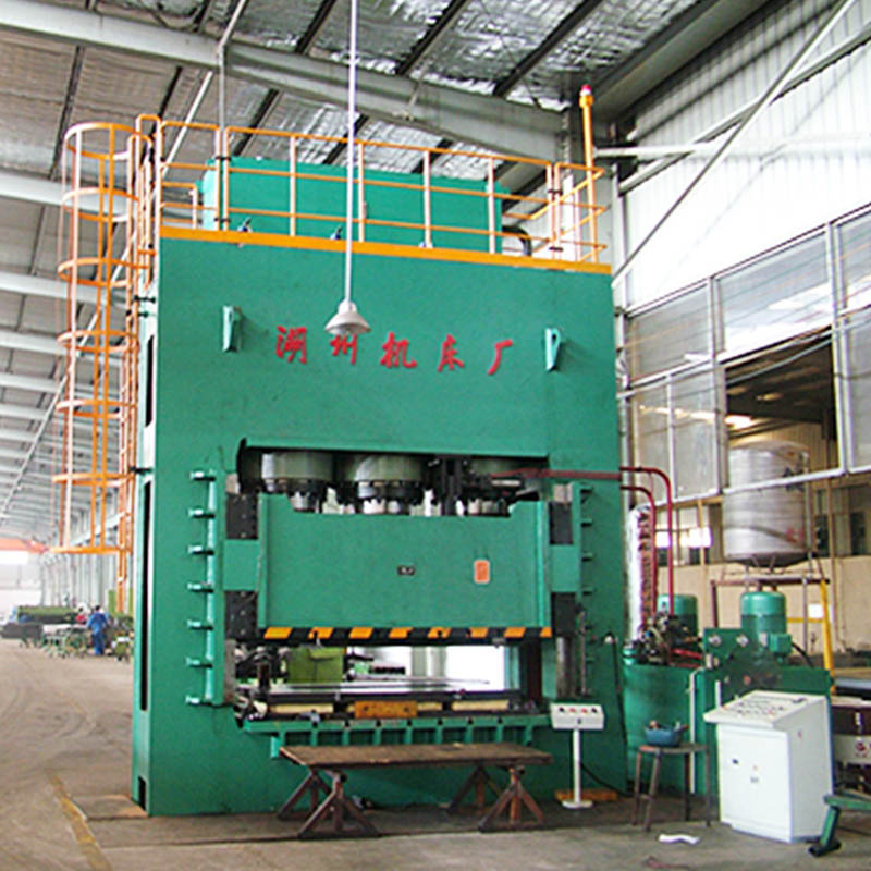
Specifying the wrong press architecture for heavy-duty forming carries significant operational risks. Structural deflection directly causes premature die wear, high scrap rates, and catastrophic tooling failure. Engineering and procurement teams face a complex challenge. You must balance required tonnage, structural rigidity, and tooling accessibility when scaling production capabilities. We exclude lighter architectures like C-frame or 2-post presses from this analysis. Heavy-duty applications, such as thick plate forming and industrial forging, demand sustained force. They require the closed-loop structural integrity found only in robust straight-side and 4-post designs. You must look past manufacturer marketing. Objectively evaluate the mechanical realities of an H frame hydraulic press versus a four column configuration based on strict, application-specific success criteria.
Terminology Clarification: Address the market confusion where some vendors erroneously market a 4 column hydraulic press as an "H-frame." A true H-frame (straight-side) relies on a rigid welded or tie-rod frame, whereas a four-column press utilizes cylindrical posts for platen guidance.
Deflection & Off-Center Loading: H-frame presses generally offer superior resistance to angular deflection and off-center loads due to full-length gib guidance.
Accessibility & Versatility: Four column presses provide 360-degree access to the die space, making them ideal for oversized tooling and automated material handling.
Capital Investment: The initial cost savings of a 4 column hydraulic press must be weighed against the potential long-term die maintenance savings provided by the rigidity of a frame type hydraulic press.
Defining the Success Criteria for Heavy-Duty Forming
Tonnage vs. Structural Rigidity
Maximum pressing force remains an incomplete metric for press selection. You cannot evaluate tonnage without factoring in the frame's ability to resist stretching and bending under load. When a hydraulic cylinder applies downward force, the press frame experiences equal and opposite reactive forces. A frame lacking sufficient rigidity stretches vertically and deflects laterally. This deflection compromises the parallelism between the ram and the bolster plate. Even a press rated for 1,000 tons fails to produce accurate parts if the frame yields under peak pressure. High-precision forming requires a structure that maintains strict dimensional stability regardless of the hydraulic force applied. When evaluating a press, engineers must request the deflection specifications from the builder. A standard acceptable deflection rate for precision stamping is 0.0015 inches per foot of bed length. Exceeding this limit guarantees tooling issues.
Material Thickness and Stroke Dynamics
Forming thick plates or executing heavy forging operations introduces unique stroke dynamics. Unlike mechanical presses that deliver peak tonnage only at the bottom of the stroke, hydraulic systems provide full tonnage throughout the entire travel. Pushing through high-tensile steel or thick alloys requires sustained force. The frame must absorb this continuous energy without oscillating or yielding. Specific frame rigidity and hydraulic cylinder configurations dictate how well the press handles these sustained loads. For example, blanking half-inch steel plate generates a massive snap-through shock when the material fractures. The press frame must absorb this reverse tonnage without cracking welds or stretching tie rods. Hydraulic presses equipped with shock dampeners mitigate this, but the underlying frame must still possess the mass to handle the vibration. If the frame deflects during a deep draw on thick material, the resulting part suffers from uneven wall thickness or tearing.
Managing Off-Center Loads
Off-center loading occurs frequently in progressive die stamping or asymmetrical part forming. When the center of the applied force does not align perfectly with the center of the press bed, it creates a tipping moment. This moment forces the ram to tilt. Managing these off-center loads requires robust guidance systems to prevent yaw, pitch, and roll. Establishing acceptable deflection limits is required before selecting a press. Consider a progressive die where the heavy drawing station sits on the far left, while the lighter piercing stations sit on the right. This creates a permanent left-heavy load. The press ram will naturally want to dive to the left. Only a rigid frame with tight gib clearances can force the ram to remain level against this uneven resistance. Failure to manage this leads to rapid die wear, galled guide pins, and out-of-tolerance parts.
Tooling Integration Requirements
The physical envelope of the press directly dictates your tooling integration strategy. Die size, loading methods, and automation requirements play a major role in press selection. You must evaluate the daylight, bed size, and stroke length against your largest anticipated tooling. The press architecture must accommodate your material handling workflow without causing logistical bottlenecks on the production floor. Consider these integration factors:
Overhead Crane Access: Requires clear vertical space above the bed for dropping in heavy dies.
Forklift Loading: Demands wide side openings and reinforced floor plates around the press base.
Automated Transfer Systems: Needs specific clearances for robotic arms, walking beams, or scrap conveyors.
Quick Die Change (QDC) Systems: Requires standardized bolster plates and hydraulic clamping circuits.
The H Frame Hydraulic Press (Straight-Side Architecture)
Structural Mechanics
The engineering of a true frame type press centers on closed-loop rigidity. These machines utilize either a fully welded steel frame or a multi-piece tie-rod construction. In a tie-rod design, heavy steel rods run vertically through the crown, uprights, and bed. Technicians pre-tension these rods to compress the frame components together. This pre-loading ensures the frame remains in compression even under maximum pressing loads. This structural approach distributes stress evenly across the heavy steel uprights. It effectively eliminates the vertical stretching and lateral bowing common in lighter designs. The straight-side architecture prioritizes absolute structural integrity over open access.
Gib Guidance Systems
Gibs provide the primary guidance mechanism in an H-frame press. These are precision-machined steel tracks that guide the ram along the uprights. Manufacturers typically employ 8-point or 4-point adjustable gibs. An 8-point system captures the ram at all four corners, both front-to-back and left-to-right. This setup maintains strict parallelism between the ram and the bolster plate throughout the entire stroke. Because gibs run the full length of the stroke, they offer continuous support. Operators adjust the gib clearances using shims or set screws to compensate for wear over time. This adjustability ensures the press maintains its original accuracy decades after installation.
Primary Advantages for High-Precision Forming
The straight-side design delivers unmatched benefits for applications requiring tight tolerances. Deep drawing operations benefit immensely from the strict parallelism, preventing material wrinkling or tearing. The gib guidance system excels at handling significant off-center loading generated by progressive dies. Specialized tasks like heavy forging, shaft correction, and profile straightening require the unyielding nature of this frame. When the tooling demands absolute precision, the H-frame prevents the die halves from shifting out of alignment. This rigidity directly translates to longer tooling life and fewer rejected parts.
Limitations and Adoption Risks
Despite its mechanical superiority, the H-frame design presents specific limitations. The solid side uprights restrict access to the die space. Operators typically only access the tooling from the front and rear of the press. This restricted access complicates die changeovers and limits material feeding options. Additionally, these presses carry a higher capital cost due to the large volume of steel and precision machining required. They also demand a larger footprint and heavier foundation requirements. You must ensure your facility accommodates the physical size and weight of this robust architecture.
The Four Column Hydraulic Press (4-Post Architecture)
Structural Mechanics
The design of a four column hydraulic press focuses on a different structural philosophy. This architecture consists of a heavy steel crown and bed connected by four precision-ground cylindrical columns. Large nuts secure the crown and bed to the threaded ends of the columns. The moving platen travels up and down these four posts. The columns serve a dual purpose. They act as the tension members holding the press together, and they serve as the guide rails for the moving platen. This design creates an open, accessible forming area while maintaining a balanced distribution of pressing force across the four corners.
Platen Guidance via Bushings
Instead of gibs, a 4-post press uses bushings to guide the platen along the posts. These bushings consist of bronze or self-lubricating composite materials. Technicians press them into the corners of the moving platen so they slide directly against the polished steel columns. While bushings provide smooth travel, they differ significantly from gibs in wear and adjustment. Bushings have a fixed clearance. As they wear down from repeated cycles, the clearance increases. You cannot simply adjust a bushing to tighten the tolerance; you must replace it entirely. This fixed guidance makes the platen more susceptible to tilting if subjected to uneven forces.
Primary Advantages for Versatility
The 4-post architecture shines in its operational versatility. The most significant benefit is omnidirectional die access. With no solid side walls, operators approach the die space from all 360 degrees. This open design makes loading oversized tooling with forklifts highly efficient. It also simplifies the integration of complex automation, such as multi-axis robots or continuous coil feeds. This architecture provides cost-effective scalability for a wide range of applications. It excels in composite molding, rubber forming, and symmetrical deep drawing where loads remain centrally focused. The open design allows for larger bed sizes without exponentially increasing the cost of the machine.
Limitations in High-Deflection Scenarios
The primary vulnerability of the four-column design emerges under severe off-center loads or snap-through shock. When a die generates an asymmetrical force, the platen attempts to tilt. This tilting puts immense lateral stress on the guide bushings and the columns. Over time, this causes accelerated bushing wear and potential scoring on the columns. Furthermore, under extreme tonnage, the columns themselves stretch slightly. If the load is off-center, the columns stretch unevenly, causing the platen to lose parallelism with the bed. This makes the 4-post design less suitable for heavy progressive stamping or aggressive blanking operations.
Head-to-Head Technical Evaluation
Deflection Resistance and Die Alignment
Comparing the deflection resistance of these two architectures reveals stark differences in dynamic forming cycles. A straight-side frame utilizes full-length gibs to resist yaw, pitch, and roll. The heavy uprights absorb lateral forces, keeping the ram perfectly parallel. In contrast, a 4-post design relies entirely on the clearance between the bushings and the columns. Under heavy off-center loads, the platen on a four-column press deflects more than an H-frame. This deflection forces the guide pins in the tooling to absorb the lateral stress, leading to accelerated die wear. For absolute die alignment under hostile conditions, the straight-side frame wins.
Accessibility and Automation Integration
Logistical differences in die changeovers heavily favor the four-column design. The 360-degree access allows operators to stage dies on any side of the press. Forklifts drive right up to the bed without interference from side frames. Robotic part transfer is also simpler to implement, as arms reach in from multiple angles. The H-frame restricts access to the front and rear windows. Implementing automation on an H-frame often requires specialized through-the-window transfer systems or front-mounted robots. If your production relies on constant die changes and oversized tooling, the 4-post press offers superior operational flow.
Maintenance and Wear Parts
Long-term maintenance requirements differ fundamentally between the two styles. Maintaining an H-frame involves periodically checking and adjusting the gib clearances. A skilled maintenance technician tightens the gibs to restore factory tolerances without disassembling the press. This process is relatively quick and inexpensive. Maintaining a four-column press requires monitoring bushing wear. When bushings wear out, you must support the platen, remove the old bushings, press in new ones, and re-level the entire platen. This labor-intensive process results in longer planned downtime. However, the open design of the 4-post press makes accessing hydraulic cylinders and valves generally easier.
Footprint and Facility Impact
Space requirements impact facility planning. An H-frame press typically requires a larger horizontal footprint due to the heavy side uprights and external tie-rod nuts. It also often requires more vertical clearance for the crown and top-mounted hydraulic cylinders. The four-column press generally offers a more compact footprint relative to its bed size. Hydraulic power unit placement also varies. On a 4-post press, the power unit often mounts on top of the crown to save floor space. On an H-frame, the unit might sit on the floor or integrate into a catwalk system, requiring additional square footage.
Technical Feature
H-Frame (Straight-Side)
Four-Column (4-Post)
Guidance Mechanism
Adjustable 8-point or 4-point gibs
Fixed clearance bronze/composite bushings
Off-Center Load Handling
Superior; actively resists yaw, pitch, and roll
Limited; highly susceptible to bushing wear
Die Accessibility
Restricted to front and rear windows
360-degree omnidirectional access
Maintenance Procedures
Adjust gibs via shims/screws (low downtime)
Replace worn bushings (higher downtime)
Optimal Applications
Progressive dies, heavy forging, high precision
Composite molding, symmetrical drawing, large beds
Capital Expenditure and Value Trade-Offs
Initial Capital Expenditure vs. Long-Term Die Savings
Procurement teams must evaluate whether the higher upfront cost of an H-frame press is justified. A straight-side press requires significantly more steel and complex machining, driving up the initial capital expenditure. A four-column press offers a more economical entry point for high-tonnage applications. However, you must calculate long-term die savings. If you run expensive progressive dies on a 4-post press, the inherent deflection causes premature wear on the die components. The cost of constantly rebuilding dies, replacing guide pins, and scrapping out-of-tolerance parts quickly eclipses the initial savings. Conversely, the rigidity of the H-frame extends tooling life, reducing maintenance downtime and improving overall yield. Align the capital investment with the specific demands of your tooling.
Evaluating the Industrial Hydraulic Press Manufacturer
Vetting vendors requires strict criteria. Look for a hydraulic press manufacturer that provides absolute transparency in their engineering data. They should willingly provide deflection ratings, typically measured in inches per foot of bed length at full tonnage. Avoid vendors who refuse to guarantee parallelism under load. Evaluate their custom engineering capabilities. A reputable builder modifies daylight, stroke, and bed dimensions to suit your exact tooling. Ensure they offer robust domestic support for spare parts, hydraulic components, and control system troubleshooting. Partnering with a proven builder of an industrial hydraulic press mitigates the risk of purchasing an under-engineered machine.
Implementation Realities and Risk Mitigation
Foundation and Rigging Requirements
Installing a heavy duty hydraulic press involves significant civil engineering realities. You cannot simply place a 1,000-ton press on a standard 6-inch factory floor. Both architectures require reinforced concrete pads designed to handle immense static and dynamic loads. Consider these installation phases:
Soil Testing: Verify the ground bearing capacity beneath the proposed installation site.
Pit Excavation: Dig deep foundation pits to accommodate lower cushions or scrap removal conveyors for large H-frame presses.
Concrete Pouring: Pour engineered, steel-reinforced concrete pads isolated from the main factory floor to absorb shock.
Specialized Rigging: Hire heavy-lift contractors to navigate overhead crane clearances and facility doors during delivery.
Operator Safety and Compliance Standards
Safety integrations are non-negotiable. The physical structure of each press type impacts guarding design. The open nature of a four-column press requires extensive perimeter guarding. You must install light curtains on the primary operator sides and hard physical fencing on the remaining sides to prevent unauthorized access. The H-frame naturally encloses the side access, simplifying the guarding strategy to just the front and rear windows. Regardless of the frame, specify redundant hydraulic valving to prevent unintended ram drops. Implement safety blocks interlocked with the main control circuit to protect operators during die maintenance.
Hydraulic and Electrical System Upgrades
The frame provides the muscle, but the hydraulic and electrical systems provide the brains. Specify proportional valving to achieve precise control over ram speed and pressure profiles. This allows for soft-touch forming, reducing shock on the tooling. Variable frequency drives on the main pump motors significantly reduce energy consumption and lower hydraulic oil temperatures during idle periods. Advanced PLC controls with touchscreen interfaces allow operators to save specific part recipes, ensuring repeatable performance across different shifts. These upgrades enhance the capability of both H-frame and 4-post architectures.
Conclusion
The final verdict depends entirely on your specific forming application. An H frame hydraulic press stands as the definitive choice for high-precision, off-center, or progressive die applications. Its rigid straight-side construction and adjustable gibs protect expensive tooling and guarantee tight tolerances. Conversely, a four column press excels in symmetrical forming, large-bed applications, and scenarios requiring maximum tooling accessibility. It offers a cost-effective solution when loads are central and uniform.
Use this shortlisting logic to finalize your decision. If your parts require progressive dies, heavy blanking, or generate severe off-center loads, specify an H-frame. If your process involves composite molding, symmetrical deep drawing, or requires loading massive dies from the side, specify a 4-post press.
Take the following next steps to advance your procurement process:
Conduct a comprehensive tooling audit to document the dimensions, weight, and off-center load characteristics of your largest dies.
Consult with a qualified industrial hydraulic press manufacturer to request application-specific deflection simulations.
Evaluate your facility's foundation capacity and overhead clearances to determine installation feasibility.
Calculate the long-term maintenance costs of your current tooling to justify the necessary capital investment in a rigid press frame.
FAQ
Q: What is the engineering difference between an H-frame and a 4-post hydraulic press?
A: An H-frame uses a rigid, closed-loop steel structure with adjustable gibs to guide the ram, offering maximum resistance to deflection. A 4-post press uses four cylindrical columns and fixed-clearance bushings to guide the platen, providing an open design with 360-degree access but less rigidity against lateral forces.
Q: Can a four column hydraulic press safely handle off-center loading?
A: It handles minor off-center loads, but we do not recommend it for severe asymmetrical forces. Heavy off-center loading causes the platen to tilt. This accelerates bushing wear, stresses the columns, and leads to premature tooling failure due to misalignment.
Q: How does frame deflection impact the lifespan of stamping dies?
A: Frame deflection forces the die halves out of parallel during the pressing cycle. This lateral shifting forces the die's internal guide pins to absorb the stress. It leads to rapid galling, dulled cutting edges, and eventual catastrophic failure of the tooling components.
Q: Why is gib guidance considered superior to bushing guidance for precision forming?
A: Gibs provide continuous, full-length support along the ram's stroke. Technicians physically adjust them via shims or screws to maintain zero-clearance tolerances. Bushings have a fixed clearance that increases as they wear, allowing the ram to tilt under pressure.
Q: What foundation requirements are necessary for a heavy duty hydraulic press?
A: Heavy-duty presses require engineered, steel-reinforced concrete pads isolated from the main factory floor to absorb shock and support immense static weight. Large models often require deep foundation pits to accommodate lower cushions, scrap conveyors, and to achieve an ergonomic working height.
Q: What should I look for when selecting a hydraulic press manufacturer?
A: Look for a manufacturer that provides transparent deflection ratings and guarantees parallelism under load. Ensure they offer custom engineering for daylight and stroke, utilize standard off-the-shelf hydraulic components, and provide strong domestic service support for troubleshooting and parts.