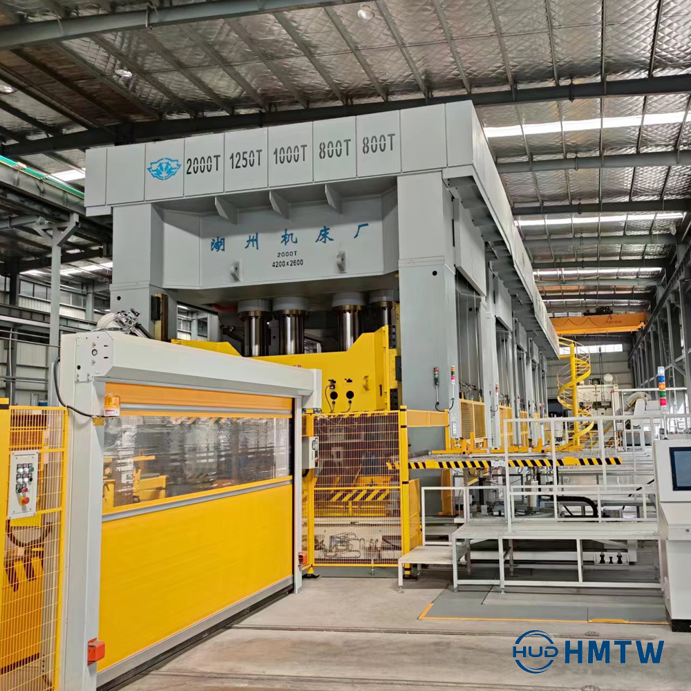
Automotive manufacturing relies heavily on lightweight, high-strength materials to meet strict safety and weight standards. Forming these advanced alloys into complex geometries with zero-defect tolerances presents a massive engineering challenge. You must achieve optimal material flow in deep-drawn parts to prevent wrinkling and tearing. At the same time, maintaining cycle times that support high-volume production schedules remains non-negotiable. Evaluating, specifying, and procuring a hydraulic deep drawing press requires a structured, field-tested framework. Mechanical precision and advanced control systems dictate the success of the entire forming process. By prioritizing sustained force application and programmable material handling, production facilities can eliminate common defects associated with deep drawing high-strength alloys. This guide breaks down the mechanics, configurations, and implementation realities of modern press systems.
Material Flow Control is Paramount: Specialized hydraulic cushions and programmable blank-holder systems are non-negotiable for managing the compression-tension forces inherent in deep drawing.
Configuration Dictates Scalability: Selecting between a single action hydraulic press and a multi station hydraulic press depends entirely on part complexity, progressive tooling needs, and volume targets.
Force Availability Over Speed: While mechanical presses offer higher cycle rates, hydraulic forming presses provide full tonnage throughout the entire stroke, essential for deep-drawn chassis and structural components.
Integration Reduces Risk: Modern automotive stamping requires seamless integration with finite element analysis (FEA) die design, automated material handling, and predictive maintenance sensors.
The Mechanics of Deep Drawing in Automotive Manufacturing
Compression-Tension Forming Realities
General sheet metal forming involves shallow bending and shaping operations. True deep drawing occurs when the depth of the drawn part exceeds its diameter. This specific process demands specialized hydraulic blank-holding to manage extreme material deformation. During the stroke, the metal blank undergoes simultaneous tangential compression and radial stretching. The press must control the blank precisely to prevent flange wrinkling from insufficient pressure and wall tearing from excessive pressure.
Complex geometries present unique manufacturing challenges. Forming deep cylindrical cups, asymmetrical dome shapes, and intricate body panels requires precise control over material thinning. As the punch pulls the metal into the die cavity, the material thickens at the flange and thins near the punch radius. Consistent force application across varying stroke depths establishes the baseline requirement for hydraulic actuation over mechanical alternatives. Hydraulic systems maintain exact pressure profiles regardless of slide position.
When troubleshooting material flow on the shop floor, operators typically monitor three primary failure modes:
Flange Wrinkling: Occurs when the blank-holder pressure is too low, allowing the material to buckle under tangential compression before it enters the die radius.
Wall Tearing: Happens when blank-holder pressure is too high, restricting material flow and causing the punch to punch through the metal rather than draw it.
Galling: Results from excessive friction between the blank and the die surface, often requiring adjustments to lubrication or die clearance alongside pressure profiling.
Automotive Application Spectrum
Press capabilities must align directly with specific automotive components. Chassis and structural components demand high-tonnage requirements to form thick-gauge, high-strength low-alloy (HSLA) steels. These parts form the safety cage of the vehicle and cannot tolerate micro-fractures during the drawing process. Body panels and closures require large bed sizes, precise slide parallelism, and impeccable surface finish preservation. Any deflection in the press frame translates directly to surface defects on exterior panels.
Complex sub-assemblies utilize the press for multi-stage forming of intricate geometries. Engineers rely heavily on hydraulic systems for die tryout and rapid prototyping. Validating 3D printed sheet metal forming dies requires the slow, controlled stroke that only hydraulic systems provide. This testing phase ensures process stability before moving production to high-speed mechanical lines. Furthermore, custom and specialty vehicles benefit from hydraulic versatility. Low-volume, custom automotive parts prioritize operational flexibility and rapid tool changes over raw cycle speed.
Automotive Component
Material Type
Primary Press Requirement
Typical Tonnage Range
Chassis Rails
Thick-gauge HSLA
High sustained force, rigid frame
1,500 - 3,000 Tons
Exterior Door Panels
Aluminum 6000 Series
Large bed size, strict slide parallelism
1,000 - 2,000 Tons
B-Pillars
Boron Steel
In-die quenching, rapid approach
800 - 1,500 Tons
Small Brackets
Mild Steel
High cycle speed, automated feed
200 - 500 Tons
Core Press Configurations for Automotive Stamping
Single Action Hydraulic Press vs. Double Action Systems
A single action hydraulic press handles simpler deep drawing tasks effectively. In this setup, a die cushion located beneath the bolster provides the necessary blank-holding force. The main ram pushes the punch down while the cushion resists, controlling material flow. This configuration simplifies the press architecture and reduces maintenance points. It suits symmetrical parts and standard drawing operations where uniform blank-holding pressure suffices.
Double action systems feature an independent outer ram for blank holding and an inner ram for the drawing process. This separation proves crucial for highly complex, asymmetrical automotive parts. The outer ram can apply varying pressures at different corners of the blank, accommodating irregular shapes like fenders or quarter panels. Selecting between these configurations involves weighing initial equipment complexity against required operational flexibility.
Feature
Single Action with Cushion
Double Action System
Blank Holding Method
Upward force from bottom die cushion
Downward force from independent outer ram
Part Complexity
Symmetrical, moderate depth
Highly asymmetrical, extreme depth
Pressure Control
Uniform or zoned via cushion pins
Highly localized corner-to-corner control
Maintenance Profile
Fewer moving parts above the bed
Requires maintenance of dual overhead rams
Multi Station Hydraulic Press for Progressive Forming
A multi station hydraulic press integrates several forming stages into a single automated transfer operation. The architecture features a massive bed accommodating multiple discrete dies. Transfer rails move the part sequentially from station to station between press strokes. This setup executes drawing, redrawing, piercing, and trimming in one continuous line. Throughput increases dramatically as raw blanks enter one side and finished parts exit the other.
Implementing multi-station setups requires careful evaluation of footprint and tooling complexity. The press frame must withstand eccentric loading as different stations perform varying operations simultaneously. Tooling designers must synchronize the stroke and transfer mechanisms perfectly to prevent part collisions. Despite these engineering demands, the reduction in floor space and manual part handling makes this configuration highly efficient for mass production.
Hot Stamping Press Integration for High-Strength Steels
The transition from cold forming to hot stamping addresses the industry's need for ultra-high-strength steels (UHSS). Crash-relevant automotive parts, such as B-pillars and roof rails, require material properties that cold forming cannot achieve without severe springback. A hot stamping press heats the boron steel blank to its austenitic state before forming. The press then forms and quenches the part simultaneously within the water-cooled die.
This process demands specific press capabilities. Rapid approach speeds minimize heat loss during the transfer from the furnace to the die. Controlled dwell times at bottom dead center ensure proper in-die quenching, transforming the microstructure into rigid martensite. Specialized thermal management systems protect the press hydraulics and seals from the extreme heat radiating from the tooling and blanks.
Critical Evaluation Dimensions: Features to Outcomes
Hydraulic Cushion and Blank-Holder Systems
CNC-controlled hydraulic cushions actively vary blank-holder pressure throughout the drawing stroke. As the punch descends and flange material decreases, the required holding force changes. Dynamic pressure control prevents the material from locking up and tearing. It also prevents the reduced flange area from wrinkling under tangential stress. Linking this dynamic control to the press PLC reduces scrap rates significantly.
Advanced lightweight alloys, particularly the aluminum series used in electric vehicles, possess narrow formability windows. These materials gall and tear easily under static pressure. Programmable hydraulic cushions allow engineers to profile the holding force precisely, matching the specific strain-hardening characteristics of aluminum. This capability determines whether a facility can successfully transition to lightweight EV component manufacturing.
Tonnage, Bed Size, and Structural Rigidity
Calculating required tonnage relies on material shear strength, blank perimeter, and drawing depth. The formula requires multiplying the total length of the cut or draw by the material thickness and the material's shear strength, then adding a safety factor for friction and die radius. Press capacities range from 200-ton pilot models for tryout to 2000+ ton production lines for full body sides. Selecting an undersized press leads to stalling and premature pump failure.
Frame construction directly impacts part quality. Monolithic frames offer high rigidity for smaller tonnage applications. Tie-rod structures, featuring a crown, bed, and uprights held together by pre-tensioned rods, minimize deflection under maximum load for large-scale operations. Bed size must accommodate the physical part, the automated transfer mechanisms, and the scrap shedding pathways. Insufficient scrap clearance leads to automated line stoppages and die damage.
Stroke Control and Slide Parallelism
Programmable stroke profiles optimize cycle times without compromising part quality. A modern press executes a fast approach to close the daylight quickly. It then shifts seamlessly into a controlled, slower drawing speed to allow proper material flow. Finally, it utilizes a rapid return to open the die for part ejection. This profiling maximizes output while respecting the metallurgical limits of the sheet metal.
Off-center loading occurs naturally in progressive dies or asymmetrical deep drawing. Active slide parallelism control utilizes proportional valves and linear encoders to keep the ram perfectly level, even when force distributes unevenly across the bed. Maintaining strict parallelism prevents premature die wear, eliminates galling, and ensures uniform wall thickness across the finished component.
Comparing Alternatives: Hydraulic vs. Mechanical Stamping
Force Availability and Stroke Dynamics
The fundamental difference between technologies lies in force distribution. A hydraulic system provides full rated tonnage at any point in the stroke. A mechanical sheet metal stamping press only delivers its maximum rated tonnage near bottom dead center (BDC). If a deep drawing operation requires high force two inches above BDC, a mechanical press may stall or suffer drivetrain damage.
Deep drawing inherently favors hydraulic systems due to the need for sustained force over a long drawing distance. As the punch pulls material into the cavity, the resistance remains high throughout the entire travel. Hydraulic cylinders maintain consistent pressure, pushing through the resistance smoothly. Mechanical presses rely on flywheel energy, which depletes during a long draw, causing speed fluctuations and potential material tearing.
Cycle Time and Production Volume Trade-offs
Mechanical presses historically held a significant speed advantage, making them the default for high-volume blanking and shallow forming. Their continuous rotary motion allows for rapid, rhythmic cycling. However, modern hydraulic advancements bridge this cycle time gap for an automotive stamping press. Servo-hydraulic pumps control fluid flow with extreme precision, eliminating valve lag.
Accumulator systems store hydraulic energy during the idle portions of the cycle. They release this pressurized fluid instantly during the rapid approach and return phases, drastically reducing overall cycle time. While a mechanical press might still win in raw strokes-per-minute for simple parts, servo-hydraulic systems provide the necessary speed for deep drawing without sacrificing force control.
Energy Consumption and Operational Efficiency
Traditional hydraulic systems utilize constant-running induction motors driving fixed-displacement pumps. This setup consumes significant energy even when the press sits idle between strokes. Variable-speed pump drives and servo-motors change this dynamic completely. The motor only spins at the required RPM to deliver the exact flow and pressure needed for that specific millisecond of the stroke. During idle times, the motor stops, dropping energy consumption to near zero.
Operational efficiency extends beyond electricity usage. Hydraulic impact mitigation extends tooling lifespan by eliminating the harsh mechanical shock at the point of contact. The programmable stroke allows the punch to contact the blank softly before building pressure. Additionally, hydraulic presses require less massive foundation reinforcements compared to mechanical presses, as they do not generate the same level of seismic vibration from heavy flywheel rotation.
Implementation Realities and Risk Mitigation
Die Setup, Tryout, and FEA Integration
Integrating Finite Element Analysis (FEA) during the die design phase predicts material thinning, wrinkling, and springback before cutting any steel. Software simulates the exact hydraulic pressure profiles and material properties. Physical die validation remains mandatory. The physical die tryout process validates the finite element-based studies, ensuring real-world material behavior matches digital simulations. Operators adjust the hydraulic cushion parameters on the hydraulic forming press to fine-tune the material flow based on physical tryout results.
Maximizing press uptime requires Single Minute Exchange of Die (SMED) capabilities. Automated die clamps secure heavy tooling at the push of a button, replacing manual bolting. Moving bolsters allow operators to stage the next die outside the press while the current job runs. Once production finishes, the bolster rolls out, the new die rolls in, and production resumes in minutes rather than hours.
Automation and Material Handling Compatibility
High-volume automotive stamping mandates seamless integration with material handling systems. Destackers separate raw blanks using magnetic fanners and vacuum cups. Robotic blank loaders position the material precisely onto the die. Inter-press transfer rails move parts between stations, and automated outfeed systems handle finished components. The press must communicate flawlessly with all peripheral equipment.
Control system bottlenecks pose a significant risk to automated lines. Proprietary, closed-loop controllers prevent third-party robots from syncing with the press stroke. Mandate open-architecture Programmable Logic Controllers (PLCs). Open protocols allow the press, the transfer system, and the safety scanners to share real-time positional data, ensuring smooth handoffs and preventing catastrophic tooling collisions.
Maintenance, Fluid Management, and Downtime Risks
Hydraulic systems face specific operational vulnerabilities. Fluid contamination stands as the leading cause of pump and valve failure. Microscopic metal shavings or degraded seal particles score cylinder walls and jam proportional valves. Seal degradation occurs from excessive heat or incompatible fluid types. Thermal management remains critical, as continuous high-pressure cycling generates substantial heat within the hydraulic oil.
Mitigation strategies require proactive engineering and strict adherence to maintenance schedules. Facilities must implement the following protocols:
Inline Particle Filtration: Install systems that meet strict ISO cleanliness codes to continuously scrub the fluid of micro-contaminants.
Predictive Maintenance Sensors: Deploy sensors to monitor vibration signatures on pump bearings, track temperature spikes in the reservoir, and measure pressure drops across filters.
Robust Cooling Circuits: Utilize either air-to-oil heat exchangers or chilled water systems to maintain optimal fluid viscosity and protect seal integrity.
Routine Fluid Analysis: Conduct monthly oil sampling to detect chemical breakdown or water ingress before it damages internal components.
Conclusion
A hydraulic deep drawing press remains the mandatory standard for automotive components requiring deep, complex geometries and precise material flow control. The physics of drawing advanced high-strength steels and lightweight aluminum alloys prioritize sustained force over raw cycle speed. By leveraging programmable stroke profiles and dynamic blank-holding, manufacturers eliminate tearing and wrinkling defects. Base vendor selection on the ability to demonstrate active blank-holder control and proven structural rigidity under off-center loads. Ensure the equipment features open-architecture controls for seamless automation integration.
Initiate feasibility studies using FEA on your most complex structural parts to determine exact tonnage and cushion requirements.
Request detailed energy consumption models focusing on servo-hydraulic efficiency metrics from potential vendors.
Schedule physical die trials with shortlisted manufacturers to validate slide parallelism and dynamic pressure control under real-world conditions.
Audit your facility's current material handling systems to ensure compatibility with open-architecture press PLCs.
FAQ
Q: What is the difference between a sheet metal stamping press and a hydraulic deep drawing press?
A: Stamping presses are typically mechanical, utilizing a flywheel for high-speed blanking and shallow forming. They deliver maximum force only at the bottom of the stroke. Hydraulic deep drawing presses use fluid power to maintain constant, full tonnage over a long stroke, which is mandatory for forming deep, complex shapes without tearing.
Q: How does a hydraulic cushion prevent wrinkling in deep drawing?
A: A hydraulic cushion applies controlled, upward pressure against the blank-holder ring. This manages the material's flow into the die cavity. By maintaining exact resistance, it prevents the outer flange of the metal blank from buckling or wrinkling under the severe tangential compression generated during the drawing process.
Q: What tonnage is typically required for an automotive stamping press?
A: Tonnage varies widely based on application. Small brackets and die tryout presses may require only 200 to 500 tons. Large body panels, chassis components, or parts made from high-strength low-alloy (HSLA) steels often require presses rated between 1,000 and 2,500+ tons to overcome the material's shear strength.
Q: Can a single action hydraulic press perform deep drawing?
A: Yes, a single action press can perform deep drawing provided it is equipped with a robust die cushion system. The cushion acts as the blank holder from below. However, for highly asymmetrical or exceptionally deep parts, double action presses with independent outer rams are preferred for better material control.
Q: Why use a hot stamping press for automotive parts?
A: Hot stamping combines forming and in-die quenching to manufacture ultra-high-strength steel parts. Heating the steel makes it malleable for complex drawing. Rapid cooling in the die transforms the microstructure to martensite. This produces exceptionally strong, lightweight parts essential for vehicle crash safety standards.
Q: How do you calculate the drawing force for a hydraulic forming press?
A: The basic calculation involves multiplying the punch perimeter by the material thickness and the material's tensile or shear strength. You must also factor in a coefficient for friction and the die radius. Engineers always include a safety margin in this calculation to ensure the press does not stall.
Q: What are the advantages of a multi station hydraulic press?
A: A multi station press allows sequential operations like drawing, redrawing, piercing, and trimming to occur automatically within a single machine footprint. Transfer rails move the parts between dies synchronously. This drastically reduces part handling, minimizes labor requirements, and increases overall throughput compared to using multiple standalone presses.